Earth Resistance Testing: Procedure and Requirements
Introduction
Testing earth resistance is a crucial step in ensuring the safety of electrical installations. These tests verify that the grounding system complies with regulatory standards, reducing the risk of electric shocks and malfunctions. This guide explains how to perform an earth resistance test, how to interpret the results, and provides information on the costs and required equipment.
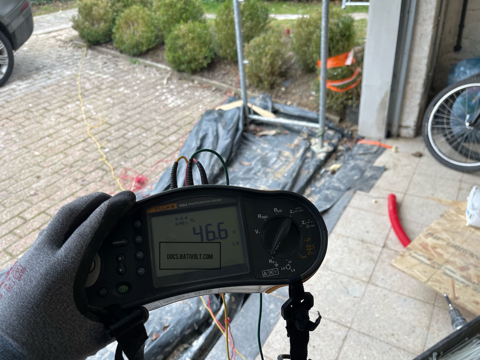
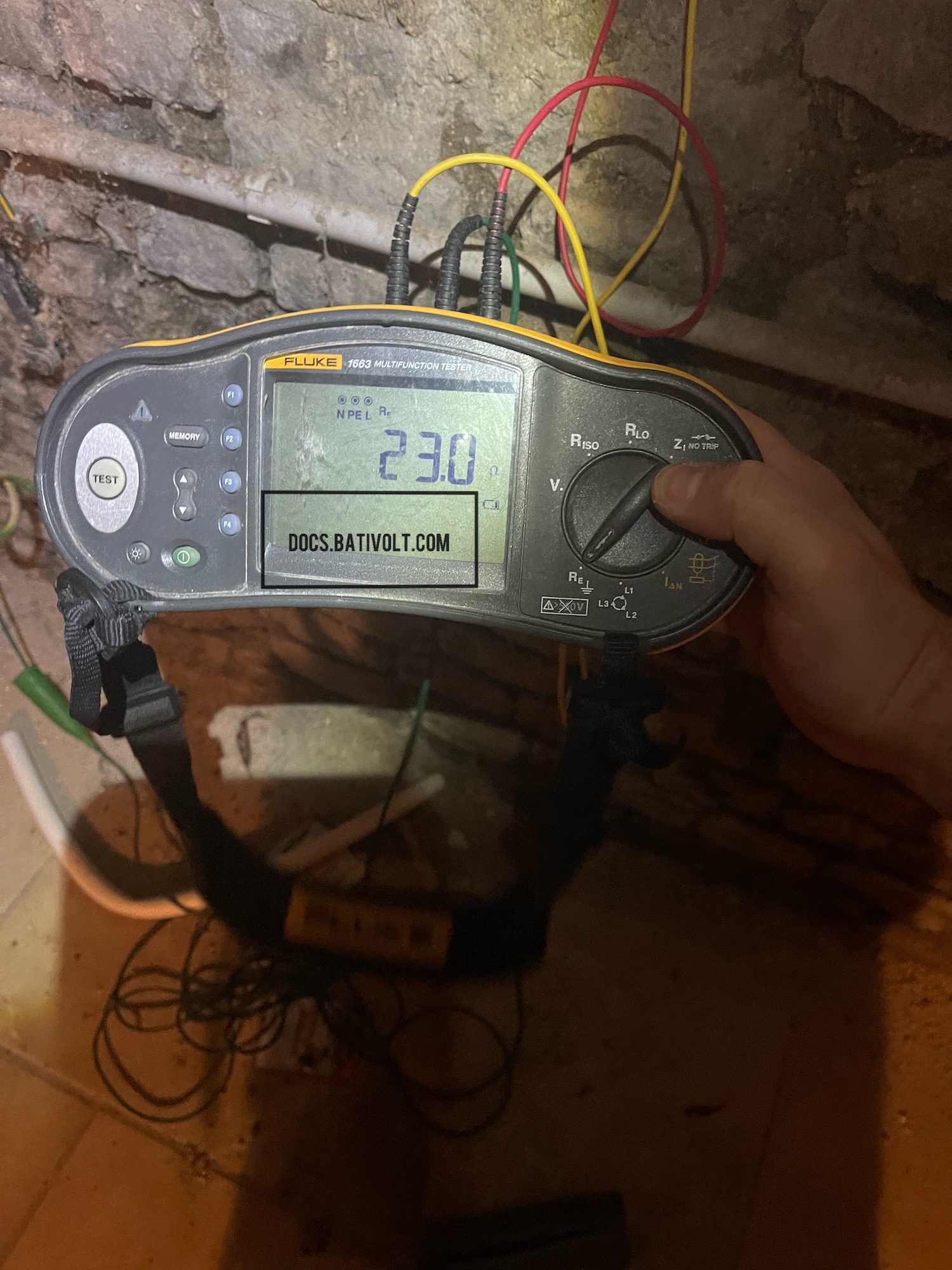
Example: Here are two earth resistance test results using a Fluke 1663 tester:
- Non-Compliant: 46.6 ohms (above the standard limit)
- Compliant: 23 ohms (below the 30-ohm threshold)
Images: Earth Resistance Test Results
Example: Here are two earth resistance test results using a Fluke 1663 tester:
- Non-Compliant: 46.6 ohms (above the standard limit)
- Compliant: 23 ohms (below the 30-ohm threshold)
1. Why Test Earth Resistance?
Earth resistance ensures that fault currents can safely dissipate into the ground. A value below 30 ohms is generally required to protect both users and equipment.
Note: Regular testing of earth resistance helps ensure that the grounding system functions properly and remains compliant with standards.
2. Required Equipment: Earth Resistance Tester
An earth resistance tester is essential for verifying the safety and compliance of an installation. Although a model like the Fluke 1663 is used in the example above, other devices can also provide accurate measurements of earth resistance.
Operation and Usage
- Preparation: Connect the tester to the test electrodes and ground rods.
- Placement of Ground Rods: Drive the rods into the soil at a specified distance from the main grounding point.
- Testing: The tester applies a voltage and measures the current, calculating the resistance using Ohm's law.
💡 Tip: Use a hammer or mallet to drive the ground rods into the soil to ensure good contact for accurate results.
Alternative: Using a Jackhammer for Ground Rod Installation
A jackhammer with a special attachment can be used to install ground rods, especially in hard soil. The attachment fits the head of the rod, allowing it to be driven quickly and evenly without causing damage.
Example Image: Using a Jackhammer for Ground Rod Installation
An illustrative photo will be added here soon. Given the extent of the documentation, some sections may temporarily lack visuals.
To support the community, you can contribute by sending your own relevant photos for this section! Send them to docs@bativolt.com, and we will include your name as a contributor. Together, let's enhance the educational experience of Bativolt!
3. Step-by-Step Testing Procedure
3.1. Site Preparation
- Clear the Ground: Ensure the soil around the rod is free of debris or insulating material.
- Rod Distance: Place the rods at a specific distance (minimum of 2 meters apart) to obtain accurate measurements.
3.2. Configuring the Tester
- Connect the Leads: Attach the Fluke 1663 tester cables to the ground terminals and rods.
- Select Test Mode: Set the tester to earth resistance testing mode.
3.3. Reading and Interpreting Results
- Compliant Result: Below 30 ohms, indicating adequate resistance.
- Non-Compliant Result: Above 30 ohms, indicating that improvements are needed to ensure safety.
Warning: If the results are non-compliant, additional ground rods may be required, or the contact with the soil may need improvement.
4. Associated Costs
The cost of an earth resistance test depends on the equipment, time required, and labor fees if performed by a professional.
4.1. Equipment Rental
- Earth Resistance Tester Rental: Approximately €50 to €100 per day.
- Earth Resistance Tester Purchase: Between €300 and €1500, depending on the features.
4.2. Installation and Additional Materials
- Ground Rods: Around €10 to €30 per rod.
- Connection Cables: Costs vary based on length and section needed, from €5 to €20.
4.3. Professional Services
Hiring an electrician to perform the test may cost between €100 and €200, including travel, labor, and the use of professional equipment.
5. Calculation Method: Ohm's Law
The tester uses Ohm's Law to calculate the resistance: R = V/I, where:
- R is the earth resistance (in ohms),
- V is the applied voltage,
- I is the measured current.
Example: If the tester applies a voltage of 10 volts and the measured current is 0.5 amperes, then the resistance is R = 10 / 0.5 = 20 ohms.
Advice: Check multiple points around the ground rod to ensure consistent values. Variations may indicate issues with the soil or the rods.
Conclusion
Ensuring compliant earth resistance is essential for the safety of electrical installations. If in doubt, or if the results are non-compliant, it is highly recommended to consult a professional. Bringing grounding systems into compliance helps prevent potential risks and guarantees user safety.
Reminder: Testing earth resistance is crucial for all installations, whether new or old. Compliant values ensure effective protection against electrical failures.
Disclaimer:
The contents of this site, docs.bativolt.com, are provided by Bativolt, a licensed electrical company. Intended for educational purposes, they are based on our interpretation and experience with the Belgian Electrical Regulations. Bativolt cannot be held responsible for any misuse or misinterpretation of the regulations or our documentation.
Copyright © 2024 Bativolt. All rights reserved.
Reproduction of the content on this site, even partially, is prohibited without prior authorization.